| Fuel tank :
A key part of any fuel system is the fuel container
itself. The debate is whether to use a modified USCG
approved fuel tank or install a racing fuel cell.
There are several benefits for retaining the stock fuel
tank in a high horsepower Marine craft. It has a larger capacity
than most fuel cells, already has a mounting location and hardware, has
provisions for filling from outside the craft, has a cap that both
vents and seals and is already on/in the craft.
The drawbacks of using a common USCG approved fuel tank
are more numerous but less obvious. The stock pick-up / pump
assembly is restrictive, requiring complete replacement with a
fabricated assembly. When using a stock tank with fabricated
pickup, unless the fuel level in the tank is � full or higher, the
internal well, which the stock pump draws from, is far too small and
poorly supplied with fuel from the rest of the tank. Faced with
the demand of a large pump, drawing through a fabricated pickup, it has
no chance of refilling fast enough to support WOT full engine
load. Under low demand, e.g. cruise type conditions, the large
volume of fuel delivered to the carburetor or rails is unused and
returned. The same fuel, picks up heat from the pump and the
rails, is constantly recycled to and from this tank, which will rapidly
increase fuel temperature. Common problems associated with stock
fuel tanks and fabricated pickups are pump cavitation, vapor lock,
varying fuel pressure, exaggerated pump wear and lean conditions during
both low and high loads. Note: Unlike a carbureted engine, any loss of
fuel supply at the in-tank- pickup will immediately result in a loss of
fuel volume and pressure at the EFI injector resulting in lean
conditions and engine damage.
Most of us will be stuck with a stock style fuel
tank since they need to be USCG approved to qualify for a marine craft
, you look at a common layout of 3/8" pick up line with anti syphon
valve as "Pick up". This pick up is restraining your fuel flow at the
same source where it should flow free. Your tank will most likely have
a 1 1/2" fill and 5/8 " vent tube molded into
the tank. Here we are still missing one more nozzle for the
cozy/warm return line.
Until the tank manufacturers have changed their tank design to
provide bigger diameter pick up lines and a return line nozzles, we can
only modify it to fit existing needs. We can use the 5/8" vent tube and
modify it to the pick up line, lets not forget to install a anti
syphon valve before we go to the filter / pump. Use the 3/8" pick up
line as vent ( make sure to get rid of the pick-up tube molded into the
tank) and "T" into the 1 1/2" fill line your return line at the
closest point to the tank. As the pump will start to pick up fuel from
the tank, the fuel volume will decrease. Any excess fuel from your
carburetor or EFI injectors will be returned into the tank and the
warmer fuel will mix with the fuel in the tank. Do not "T" your return
line just before the fuel pump since that will send high amounts of
fuel continuously through the fuel pump to heat up more till it will
reach critical temperature. Unfortunately with this
modification, you have changed the once USCG compliant tank into
your own piece of art.. Even though this piece of art might do
the job but you are not USCG compliant anymore.
With this set up the primary problem of heat soak is minimized.
However, this is still a compromise at best, requiring fuel levels be
maintained above � for normal low engine load, above � to � for
racing . In all serious racing applications the correct fuel cell
is highly recommended.
|
| Fuel Intake
filter:
Or intake filter - Most people regard fuel filter as the
first line of defense against contaminated fuel. Personally, I believe
it is the last line of defense which often produces more problems
than it solves. This part of the fuel system file is regarding non
diesel application which have a bigger set of problems.
Before you actually fill fuel in your tank, make sure the tank and the
fuel is clean. Use a strainer every time to fill the tank and
close fill cap after filling.
A good recommendation from Aeromotive fuel system
is that the filtration media to be used on the inlet side of a
fuel pump may be no smaller than 100 micron and must have an element
surface area of 60 square inches or more. Any filter element not
meeting these criteria may fail to flow the full volume of a high
capacity fuel pump being used, resulting in cavitation at the
pump inlet. Most high capacity fuel pumps are extremely efficient by
design, allowing them to create high pressure on the outlet and high
vacuum on the inlet side, if restricted. Cavitation can be to a
pump like detonation is to an engine and occurs when the liquid being
pumped reaches a temperature where it boils and starts to
vaporize. The temperature at which any liquid boils varies with
pressure. Recall that water in a radiator is purposely
pressurized to raise the boiling point. When was the last time
your high pressure EFI system vapor locked? Keep in mind, as a
pump pushes it has to pull. When a pump has to pull too hard
acquiring fuel, a vacuum or low-pressure area develops at the
inlet. The better and more efficient the pump is, the lower inlet
pressure will fall. The boiling point of any liquid fuel in this
low-pressure zone falls as well. With a highly efficient pump,
inlet pressure can get so low that fuel will boil and the pump will
cavitate at normal operating temperatures. Today's ultra-high output
engines require equally high efficiency fuel pumps. Failure to
install them properly can be costly in two ways: First, during
cavitation the engine may experience a momentary lean condition (loss
of liquid fuel pressure and volume). Second, excess heat and
friction will build in the pump, causing damage and eventual
failure. If you feed your pump properly it will feed your beast
for years to come! Review your installation and make sure the
pump is mounted where gravity will help push fuel to the inlet, use the
correct size AN line between the tank and the pump and install filters
that flow the necessary volume freely. In some marine applications you
will find a whole set of filters before the actual pump, make sure your
filters are cleaned and cartridges replaced on a regular basis.
|
| Fuel pump :
The performance of your whole fuel system depends upon
the fuel pump. Selecting the right fuel pump is of the out most
importance to your high speed water craft's performance.
The critical factors that effect fuel pump selection are
numerous. In the past, fuel pump manufacturers have rated their
offerings based on gallons-per-hour, free-flow (no test pressure), and
with no reference to test voltage. In the real world, this gives
no indication of the horsepower that could be supported by such a pump.
The key variables that determine which fuel pump is suitable for a
particular engine combination are:
- Engine flywheel horsepower.
- Engine fuel efficiency, commonly referred to as BSFC
or Brake Specific Fuel Consumption.
- Maximum fuel system pressure and the pump's flow
volume at that pressure.
- Available voltage at the pump under engine load and
the pump's flow volume at that voltage.
The first step is to establish how much horsepower will be produced and
the amount of fuel required to support it. To be safe, start by
estimating HP on the high side and efficiency or BSFC on the low
side. A typical gasoline engine will use less than 1lb of fuel to
make 1 HP for 1 hour, so expect the BSFC number to be less than
1. Different engine combinations, power adders, even fuel octane
ratings and tuning approaches will have a profound impact on
BSFC. Consider this carefully when choosing a fuel pump.
You may use the following information as a guideline,
however these are simply observations. The best, and our
recommended, method of establishing actual BSFC is through proper
flywheel dyno testing.
- Naturally aspirated engines are normally most
efficient with a BSFC between .4 and .5 lbs/hp/hr.
- Nitrous combinations use a little extra fuel and
often develop a BSFC from .5 to .6 lbs/hp/hr.
- Forced induction engines are usually least
efficient and BSFC ranges from .6 to .75 lbs/hp/hr.
Using 650 HP, lets figure the fuel requirement for the most vs. the
least efficient engine combination.
- 650 HP multiplied by a .4 BSFC equals 260 lbs
of gasoline.
- 650 HP multiplied by a .75 BSFC equals 487 lbs of
gasoline.
As you can see, the amount of fuel required to support two different
engines, each making the identical amount of HP but with very different
fuel efficiencies, virtually doubles the volume of fuel required!
Note: It is equally important to consider BSFC when
determining minimum injector size. To calculate, divide the lbs
of gasoline required by the number of injectors used. If you are
estimating, it pays to be safe. Many engine builders will add a
percentage to total fuel pump volume for safety and then divide the
minimum injector by .8 in order to target about 80% injector duty
cycle. This allows consistent injector performance, cooler
operation for enhanced durability and leaves about 10% for unexpected
power.
For example:
- 650HPx.4 = 260lbs. 260lbs/8
injectors=33lbs/hr. 33/.8=41lb/hr injector @ 80% duty cycle.
- 650HPx.75=487lbs. 487lbs/8
injectors=61lbs/hr. 61/.8=76lbs/hr injector @ 80% duty cycle.
It is imperative to consult with an experienced engine builder when
estimating HP and making these calculations. There's a lot at
stake and errors can result in serious harm to the engine and those
around it.
Determining the fuel volume necessary for a particular
engine is the first step in selecting a fuel pump. If the
combination is naturally aspirated, does not use rising fuel system
pressure and has a correctly sized alternator in good working condition
it may be OK to stop here. If not, there's still more to
consider.
The second step is to establish what the base fuel
pressure will be and if, as with forced induction or certain "dry
nitrous" kits, pressure will be required to change with engine load.
How does fuel pressure affect pump delivery? You can bet that as
system pressure goes up the pump’ volume will go down.
To illustrate this, take one of the most popular and
efficient EFI pumps on the market, Aeromotive’ A-1000 part
#11101. Lets examine various pressures to demonstrate the effect
this has on flow volume:
- Carbureted, Nat Aspirated, 9psi and 13.5v, volume
791lbs/hr. 1,582 HP @ .5 BSFC.
- EFI, Nat. Aspirated 43.5psi and 13.5v, volume
614lbs/hr. 1,228 HP @ .5 BSFC.
- 20psi boost/1:1 Regulator, intercooler, 60psi and
13.5v, volume 529lbs/hr. 881 HP @ .6 BSFC
- 10psi boost/4:1 FMU, intercooler, 80psi and 13.5v,
volume 426lbs/hr. 710 HP @ .6 BSFC
- 6psi boost/8:1 FMU, intercooler, 91psi and 13.5v,
volume 370lbs/hr. 616 HP @ .6 BSFC
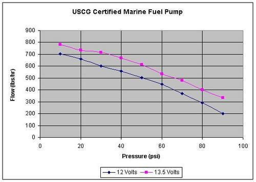
Measuring a high efficiency fuel pump such as "HP Marine
USCG Fuel Pump P/N 11108" , from 9psi to over 90psi, flow volume is
reduced a total of 53%. Comparing volume at 60psi for a high
boost kit with correct injectors to 90psi for a low boost application,
with small injectors and an FMU, volume is reduced by 28%.
 Clearly the effect of rising fuel pressure has significant impact on
flow volume. What is not shown (and rarely published) is the
devastating impact this has on less efficient, traditional pumping
mechanisms. It is obvious that eliminating unnecessary fuel
pressure rise, e.g. removing an FMU and installing the correct
injector, increases flow, maximizing the HP potential of any fuel
system.
Clearly the effect of rising fuel pressure has significant impact on
flow volume. What is not shown (and rarely published) is the
devastating impact this has on less efficient, traditional pumping
mechanisms. It is obvious that eliminating unnecessary fuel
pressure rise, e.g. removing an FMU and installing the correct
injector, increases flow, maximizing the HP potential of any fuel
system.
This brings us to our third fuel pump performance
factor; voltage supply as measured at the fuel pump terminals.
Voltage to an electric motor is like fuel pressure to an injector, more
pressure in equals more volume out. Higher voltage at the pump
terminals increases motor torque, resulting in more rpm and an
increased flow volume for a given pressure. To illustrate this,
lets use again the above Aeromotive marine fuel pump at 80psi will see
a 40% increase in volume when voltage is increased from 12v to
13.5v. This factor is often overlooked and can make or brake pump
performance, especially at high pressures. The key here is to
figure flow at voltage if an alternator is used or not. As
Hovercraft can fly where no other transportation means can go - you
know you are the only one out there.
Just imagine if your alternator fails and and on your return trip
voltage will drop. If the voltage of your slowly discharging battery
reaches the critical aspect where your pump can't build sufficient
pressure to supply the engine with fuel. I guess you are stuck for
good. In case of a recreational craft you can make a nice adventure out
of it, in case you run a charter / taxi service you will need
good legal representation.
Dynamic vs. Static
fuel systems: EFI efficiency for carburetors.
CARBURETORS STILL RULE in many forms of racing and on
many cruising machines. Those who choose (or are required) to run
a carburetor are turning to expensive, custom-built models for better
performance. Often the custom shop will advise a fuel pump
upgrade, usually suggesting a pump rated to flow as much as 4-6 times
the amount necessary to support the engine’ horsepower. Normally
the quick explanation for this is the need to overcome acceleration
G-forces.
Hold in mind you can spin your Hovercraft like a donut on water or hard
surfaces. That you can do this is your pure fun, pleasure and
entertainment - just under this condition your standard fuel pump has
to work overtime. Your fuel tank is most likely located as close as
possible to the CoG of your craft, way down in the bilge area. Your
fuel pump is located aft at the engine compartment. As long as the tank
is aft of the Cog centrifugal forces are no major aspect, once the fuel
tank is forward of the CoG centrifugal forces will first help the pump
- before she has to overcome the centrifugal forces which force the
fuel away from the CoG.
The least aspect you want to worry while you enjoy the donut flight is
a dying engine because of low fuel pressure. Which would eliminate any
control over your craft and most likely a bit wet plow in as you loose
lift air.
The fuel systems first priority is to keep the floats
from running low enough to uncover the main jet, running the engine out
of fuel. Traditional, static systems do a fair job of this.
The second, more difficult priority is keeping the fuel level optimum
in the bowl. It may not seem significant but the weight of fuel
above the main jet does impact fuel flow through it, and therefore the
air/fuel ratio of the engine under load. The sophisticated
carburetor racer knows the float bowl must always be as full as
possible. This is critical if engine tune is to be held across
the rpm band, achieving peak performance throughout the race. An area
of special focus for racing crafts is the time before
getting over hump speed following launch. Here the typical static
fuel system struggles. The fuel is standing in the line, barely
moving and to make matters worse, the static style regulator places the
check valve between the fuel pump and carburetor, restricting fuel flow
across the board. To combat this, fuel pressure in a static
system is always held higher from the pump to the regulator (12-60psi)
than it is from the regulator to the carburetor (3-7psi). This
higher line pressure is necessary for two reasons, one to start flow
against G-force and two, to push fuel through the restrictive regulator
valve. A return style regulator places the inlet and outlet ports
above the check valve with only the return volume having to flow
through the restriction. As a result, the pressure from the pump
to the regulator is the same as from the regulator to the carburetor
(3-7psi), allowing the pump to speed up, increasing volume
significantly, and supplying full output directly to the float bowls at
all times.
The benefits of a dynamic, return style fuel system are
numerous, including longer pump life, a marked increase in pump to
horsepower ratings (allowing smaller, lighter pumps to fuel more HP),
even quieter pump operation is common. Ultimately, combining a
high quality marine fuel pump and return regulator into a dynamic
fuel system significantly improves average float level, fueling the
bowls more quickly and consistently. The bottom line is the
finish line and getting there first with a more constant air/fuel ratio
across the rpm band and more predictable power all the way down.
|