This script shall give you a basic idea of a simple hydraulic
system ( also known as fluid power system ) for single engine
hovercraft. The hydraulic system is used for separate lift fan
operation.
It is not a working copy to set up any system and shall provide you
only with the basic idea and some tips in the layout - please consult a
hydraulic specialist for detailed calculations and project specific
layout.
You will find some required calculations and formulas in
the linked pdf files.
The basics :
A hydraulic system consist of a hydraulic pump and motor.
The pump is attached to
the main engine. The shaft of pump is connected to the engine shaft via
reduction or belt drive.
With each revolution of your main engine, the hydraulic pump is brought
into pumping motion.
It is important to take care of the pump max. rated RPM which in most
cases, will require a reduction drive. Hold in mind that you will need
adequate RPM for your lift unit before you reach high RPM on your
thrust output shaft. As well as max. thrust shaft RPM should not exceed
max. rated pump RPM.
The pump is connected via
hydraulic fluid line to the hydraulic motor. This is your
high pressure line. For further reference please use : Eaton Pressure-Flow Compensated Piston Pumps all
credits to the original source.
The motor most likely
will be attached to the fan shaft directly or in the shortest possible
way. As the hydraulic pump builds up pressure with each rotation,
the high pressure line transfers this pressure to the intake side of
the motor which will start turning in a nearly equal manner ( minus
loss of friction in the line,...). For further reference please see
: Eaton Medium Duty Piston Motor - all credits to
the original source. The low pressure line is attached to the motor's
exit port and it will transfer the hydraulic fluid back to the pump as
seen in layout 1.
Alternative supplier are :
POCLAIN
HYDRAULICS INDUSTRIES
Sauer-Danfoss
CROSS
Manufacturing, Inc.
KNF Neuberger, Inc.
(USA)
Parker Mobile Hydraulics
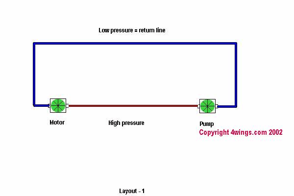 This is the most simple set up of fluid power in a closed system. Kind
of stripped down basics which will work on very low hp
application and with generally no major control over your system.
This is the most simple set up of fluid power in a closed system. Kind
of stripped down basics which will work on very low hp
application and with generally no major control over your system.
To set up your system you need to know the max. HP and RPM on your
motor side - once this is known you can work yourself to the pump side.
I hope you could still follow so we can start to complicate this quite
simple system a bit.
Lets start with the motor - what else is there to take care of besides
low weight and long lifetime for a reasonable price?.... Most motors
won't be sitting on the shelf and have a 8 - 10 week delivery time - so
it is wise to get the right unit in the first place. Make sure you know
the shaft turning direction, location of the motor and most appropriate
( high pressure and low pressure ) port direction so you can reduce 90
degree elbow on the high pressure side. Make sure your drain port
point's up to drain air from your hydraulic system. Last but not least
motor attachment is important.
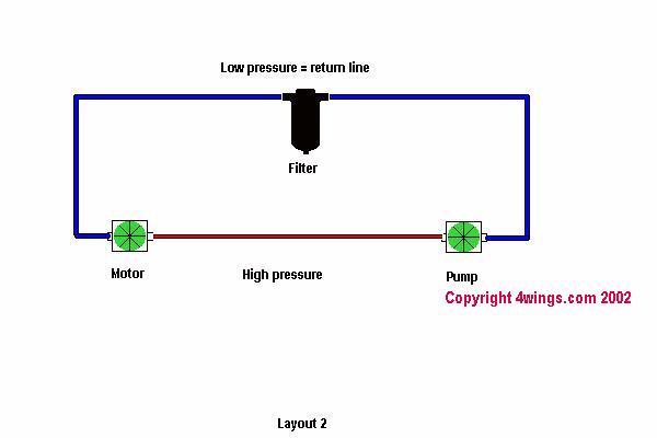
Filter:
Once we have this selected it is wise to think about the most important
medium in the system and that is your hydraulic oil ( try to use a good
non foaming oil ) . With the use of pump and motor you will get small
amounts of abrasion particles in your hydraulic oil - these tiny
buggers surf your oil and get pumped in equal manner through your
system as the oil it is in - so the use of a filter unit will increase
the lifetime of your hydraulic pump and motor and allow these buggers
to get out of the system. The filter unit will provide a certain amount
of resistance to your hydraulic oil flow.
For further reference please see : Low,
Medium & High Pressure Filters from Eaton Hydraulics - all
credits to the original source.
Your filter unit should be on the low pressure side - as seen in
Layout 2 - and is most likely close to the pump. Make the filter unit
easy accessible to change filter cartridges on a regular basis. As your
filter clogs up over time, resistance will increase in your system.
Other aspects you want to know about your hydraulic oil is
hydraulic oil pressure, hydraulic oil flow rate and the
temperature of your hydraulic oil.
In general - the more you know about your hydraulic oil the easier it
is to avoid expensive components failure.
Alternative supplier :
HYDAC TECHNOLOGY
So we covered motor aspect, oil and some means to hold
it clean ... now lets look at the
hydraulic hoses ...
somehow we need to get the hydraulic oil from point A ( pump ) to point
B ( motor ) and again back through a few obstacles. Hydraulic hoses
need to have adequate cross section to reduce friction in the line (
friction = resistance = heat build up in your oil) For further
reference please see : Velocity and Pressure drop in pipes and especially
at the section : FLOW / VELOCITY NOMOGRAM - as well as : SAE
Hydraulic hose specifications (SAE J517) . Select the appropriate
cross-section from your motor's maximum required GPM. and PSI range.
Try to lay the high pressure line as straight as possible from pump to
motor. Try to avoid 90 degree elbows in your high pressure line. Now
you have the theoretical location of your hydraulic line - so check if
the hydraulic hose will be able to flex around all corners it is laid -
some high pressure lines have quite big minimum radius. You can bend
them but do not underestimate this and try to take care of it before
hand. A Hovercraft specific problem in the layout of your hydraulic
system is the balance of your craft ( CoG ). As your hydraulic pump
will be attached by some means to your main engine, it is most likely
off center. Your motor on the other hand will be either on Centerline
or off centerline - all are fixed weights which won't change during
operation - the location of the hydraulic lines allows you to
compensate your balance to a certain extent - low pressure lines are
lighter and more flexible than the high pressure lines. Last but not
least the common sense suggestions - don't run your hydraulic
lines under your fuel tank since hydraulic oil warms up quite
considerable and it is not the safest way to fly with hot fuel ...but
who knows some might enjoy an extra boost.
So far we have a system which has no leaks. But over the
service life of your system, this might change. As well as for
hovercraft applications you will run on high RPM = high GPM. =
relatively high PSI level which will break down your hydraulic oil ...
- the means to increase the lifetime of your pump and hydraulic
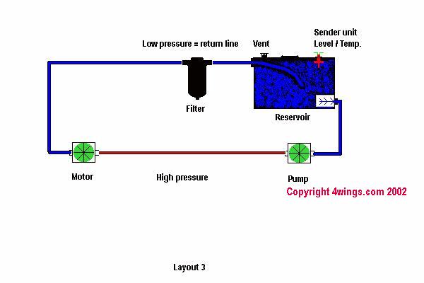
oil is a hydraulic oil reservoir tank.
This tank holds an amount of hydraulic oil and is vented to the
atmosphere. Unfortunately in a weight sensitive Hovercraft this tank is
dead weight and not appealing et all. Also it is a fact that custom
made tanks are not cheap. A good holding tank needs to have
certain features. The return line fitting which is attached to your
hydraulic hose, an internal extension which should extend in the
tank to the bottom of the tank to reduce foam build up. Internal thread
on the oil pick up side to attach a filter cat ridge, as well as
external threaded fitting to attach your hydraulic line feeding
your pump. As seen in figure Layout 3. The tank has to be located
above the pump to allow a gravity feed of hydraulic oil to the
hydraulic pump. An inspection hatch big enough to pass your hand
through ( a bit bigger would be handy so you don't loose your skin if
you clean your tank ). A vent on its highest point . And if you want to
go fancy, a thread to attach an oil level / temperature sensor would
make it safer. So you see we ask for a lot from the poor builder of
these tanks.
You can use an alternative with a basic factory tank
which has inline filter on the pick up side. But this will reduce the
life span of the tank. You must also discharge all the build ups
from the tank in an environmentally safe manner.
The sender unit in your
tank is more or less nothing more than an electric switch .
You have to determine first hand if the switch shall interrupt the
circuit ( as it would be useful if you run your ignition system over
the switch ) or close the circuit ( which is the case for a dashboard
emergency light or sound which should be activated when your level goes
low ) .
The appealing version is that in case the oil level drops ( the system
has a leak ) the sender unit would stop the main engine and damage
could be reduced to a minimum ... or you can run a red light to your
dash board ...... glue your eyes to it and hope you react quicker as
your pump is pumping the left over hydraulic oil out the leak..
Alternative supplier :
Temposonics -
Even if our basic system got now quite complicated and
fancy - we still have no means of actual control of the system = any
difference in the RPM on the hydraulic pump shaft equals to
equivalent RPM change on the hydraulic motor shaft. The only means of
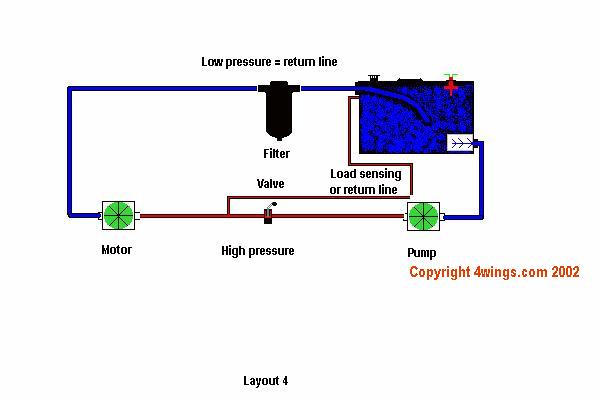
control in this aspect is a
Valve in the high
pressure line which regulates the fluid flow. For further reference
please use Vickers valves file - all credits to the
originator.
The valve - as seen in Layout 4 -should be the only component
between pump and motor in the high pressure side of the system. All the
valve does is to reduce or open the fluid flow to the hydraulic motor
but it cannot increase the flow beyond the pump capacity according to
it's input shaft RPM. The excess hydraulic fluid will be returned into
the holding tank. This process will heat up your hydraulic oil
considerably and more or less you burn unnecessary HP into heat. An
alternative is to use a pressure flow compensated pump with a load
sensing line as described in : Eaton Pressure-Flow Compensated Piston Pumps pages 25
and down - which will adjust fluid output according to
system requirements. But this variation exceeds the basic layout of
this file and might just complicate it unnecessarily.
Alternative supplier :
Marwin Valve
Flow-Tek
Conbraco
Kepner Products
Company
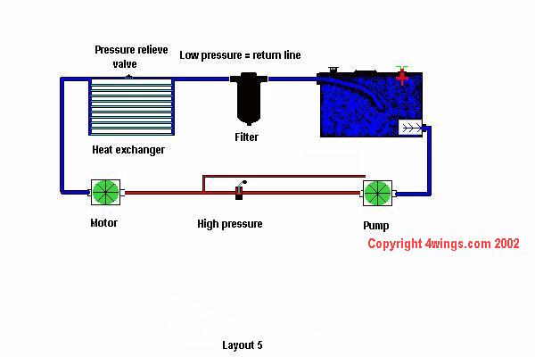
As you have seen in the description of most components -
they all have the nasty habit of changing a small amount of energy into
heat -for further reference please see : COOLING AND HEATING - from friction in the lines
to resistance in the filter units - your hydraulic oil will heat up
considerably if you have the system running on high RPM. This
heat needs to be anticipated to the environment via an adequate heat exchanger which will hold your
hydraulic oil temperature as low as possible. For further reference see
: Heat Exchangers for small systems or: Heat exchanger for bigger systems The heat
exchanger will be located in the low pressure side of your system and
either you have to use a heat exchanger with relief valve as seen in
Layout 5 - in case the unit clogs up - or two units in parallel. All
heat exchangers need direct airflow = airflow through the unit and not
over the unit which is something we do not really like to provide in
Hovercraft where we try our best to produce the highest mass flow of
air we can achieve with our HP.
This is a basic explanation of hydraulic systems , in case it
created a desire to get a more in depth knowledge , please
download the following file : "Hydraulic
systems in aircraft"
Distributor for hydraulic components :
Small HP ratings :
Northern
Tool
General aspect / high Hp ratings :
Motion
Industries
Unfortunately their web site is as useless as their service and staff
is useful - so just look up your nearest Service center and get "hands
on" with them.
|